

Development history and principle of MEMS flow sensor
Release time:
19 Jul,2024
Summary
Part.1
Development History
The development history of MEMS (Micro-Electro-Mechanical Systems) flow sensors can be traced back to the 1950s and 1960s. With the advent of integrated circuit chips, people began to explore the possibility of creating tiny mechanical structures and systems on chips. This idea of using semiconductor materials to create electronic and mechanical structures laid the theoretical foundation for the birth of MEMS technology.
In the 1980s, with the advancement of microfabrication technology, various MEMS devices such as vibration sensors, flow sensors, and print heads were successfully developed. Entering the 1990s, the United States clearly proposed the concept of MEMS and promoted the rapid growth of this technology. After the 21st century, MEMS technology has developed rapidly, its application fields have continued to expand, and it has become a multi-billion dollar emerging industry.
In the development process of MEMS flow sensors, there have been many technological innovations and industrial waves. Especially driven by the automotive industry and consumer electronics products, MEMS flow sensors have been widely used and continuously optimized. Today, MEMS flow sensors have become important equipment in the field of gas flow measurement, with continuously improving performance, gradually decreasing costs, and expanding application fields.
Part.2
Working Principle
A MEMS flow sensor is a flow measurement device based on micro-electromechanical system technology that determines flow rate by measuring the physical effects generated when fluid passes through the sensor. According to different measurement principles, MEMS flow sensors can be divided into various types, the most common of which are differential pressure MEMS flow sensors and thermal MEMS flow sensors.
1. Differential Pressure MEMS Flow Sensor
Differential pressure MEMS flow sensors measure flow rate by measuring the pressure difference generated when fluid passes through the sensor. Its working principle is as follows:
-
Sensor structure: Differential pressure MEMS flow sensors usually consist of two or more miniature channels, one of which is called the "detection channel" and the other is called the "reference channel." These channels are connected by tiny pores or miniature valves.
-
Fluid entry: After the fluid enters the sensor, it is divided into the detection channel and the reference channel.
-
Pressure difference generation: When the fluid passes through the detection channel, a certain pressure drop will be generated due to the geometry of the channel and the velocity of the fluid. The reference channel is relatively smoother, with lower pressure.
-
Pressure sensor: Pressure sensors are installed at both ends of the detection channel and the reference channel to measure the pressure difference between the two ends of the channel.
-
Pressure difference conversion: The sensor converts the measured pressure difference into an electrical signal, which is amplified and filtered by the processing circuit, and then output.
-
Flow rate calculation: According to the known sensor characteristics and fluid mechanics principles, the pressure difference is converted into the flow rate of the fluid using a calculation formula.
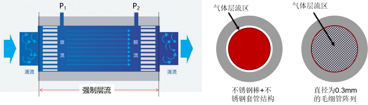
The advantages of differential pressure MEMS flow sensors are their simple structure, low manufacturing cost, and fast response speed. However, it is more sensitive to changes in the viscosity and density of the fluid and needs to be calibrated and corrected to obtain accurate flow measurement.
-
Thermal MEMS Flow Sensor
Thermal MEMS flow sensors use the heat conduction effect when fluid passes through the sensor to measure the flow rate. Its working principle is as follows:
-
Sensor structure: Thermal MEMS flow sensors usually consist of two or more miniature resistance temperature detectors (RTDs), which are fabricated in miniature channels and in contact with the fluid.
-
Heating element: One of the resistors acts as a heating element, generating a certain temperature difference by heating.
-
Temperature measuring element: Other resistors act as temperature measuring elements to measure the temperature change when fluid passes through the sensor.
-
Heat conduction: When fluid passes through the sensor, the temperature difference causes heat to be conducted into the fluid, causing the temperature of the temperature measuring element to change.
-
Resistance change: The resistance of the temperature measuring element changes with temperature. By measuring the resistance change, the flow rate of the fluid can be determined.
-
Circuit processing: The sensor converts the measured resistance change into an electrical signal, which is amplified and filtered by the processing circuit, and then output.
-
Flow rate calculation: According to the known sensor characteristics and heat conduction principles, the resistance change is converted into the flow rate of the fluid using a calculation formula.
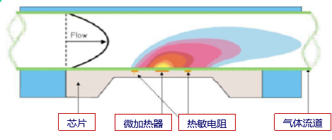
The advantages of thermal MEMS flow sensors are that they are insensitive to changes in the viscosity and density of the fluid and are suitable for various fluids. However, it has higher requirements for the heating power of the sensor and the accuracy of temperature measurement, and needs to be calibrated and corrected to obtain accurate flow measurement.
Part.3
Summary and Outlook
As an important application of micro-electromechanical system technology, MEMS flow sensors play an important role in the field of gas flow measurement. With continuous technological advancements and market expansion, the performance of MEMS flow sensors will continue to improve, costs will further decrease, and application fields will become broader. In the future, MEMS flow sensors will be fully integrated with other cutting-edge technologies such as 5G and artificial intelligence to explore more new application scenarios and make greater contributions to industrial and social development.
Part.4
Qingdao Xinnovis Thermal MEMS Technology
Qingdao Xinnovis Microsystem Technology Co., Ltd. products use MEMS chip principles, based on MEMS technology, and use finite element simulation size optimization. They adopt a high-sensitivity suspended diaphragm structure and deposit a semiconductor coating to improve chip reliability. The MEMS thermal differential flow sensor is based on the theory proposed by Thomas that "the heat release or absorption of a fluid is proportional to its mass flow rate." It uses the temperature field distribution on both sides of the micro-heater during gas flow to inversely deduce the flow rate. Unlike capillary structures or differential pressure structures with large pressure drop flow path designs, it uses a straight-through flow path structure design to achieve unprecedented ultra-low differential pressure control.
Using the deformation of the piezoelectric film to accurately control the flow rate, the manufacturing process is simple, reducing costs, and can measure very small flow rate changes, improving the measurement accuracy of the mass flow controller, better controlling the production process, and improving production efficiency and product quality.
Advantages:
① MEMS chips have a higher signal-to-noise ratio, and the chip's thermal capacity and thermal response are far smaller than those of similar products based on the capillary principle, resulting in faster response speed and a better range ratio.
② Gas flow monitoring using temperature sensing elements is cost-effective, and damaged components can be replaced individually, which helps reduce maintenance costs.
③ Strong anti-pollution capability. MEMS MFC does not have capillary blockage problems (and does not even require a filter mesh).
④ On-chip temperature compensation redundancy design is adopted, with an extremely low temperature drift coefficient, ensuring that the error within 0-50℃ can be kept within ±1%FS.

More News

Tel: 400 006 6550
Office Address: 12F, Building I, International Innovation Park,
177 Songling Road, Laoshan District, Qingdao, Shandong, China